Page 822 - Softbound_Edition_19_en
P. 822

Pressure relief valve
                                                                                        Pressure relief valves                                                                                                       Pressure relief valves

                                        2
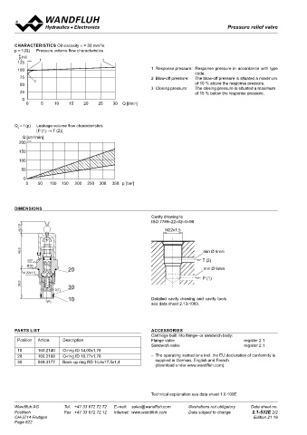
       CHARACTERISTICS Oil viscosity υ = 30 mm /s                                                                                  Vented relief valve
       p = f (Q)    Pressure volume flow characteristics         P(1)                                                              Screw-in cartridge
        P  [ % ]                                                                                                                                                                 M22x1,5
        P A     1                        2                                                                                         •  Pilot operated
        125  K0924                                                                                                                 •  Q     =   80 l/min                          ISO 7789
        100                                                 1  Response pressure:  Response pressure in accordance with type       •  p max    = 400 bar
                                                                             code.                                                    max
         75                                                 2  Blow-off pressure:   The blow-off pressure is situated a maximum    •  p     = 350 bar
                                                                T(2)
              3                                                                                                                       N max
         50                                                                  of 10 % above the response pressure.
                                                            3  Closing pressure:   The closing pressure is situated a maximum      DESCRIPTION                        FUNCTION                           APPLICATION
         25                                                                  of 15 % below the response pressure.                  Spool type pilot operated relief valve, vented.   If the operating pressure exceeds a set value,   To  limit  the  operating  pressure  in  hydraulic
          0                                                                                                                        Thread M22x1,5 and cavity in accordance with   the pilot part opens. A control fluid then starts   systems. The valve function can be remote
           0     5    10    15   20    25    30  Q [l/min]                                                                         ISO 7789. The valve is available in 2 different   to flow and relieves the back of the spool in the   controlled via connection x. When relieving/
                                                                                                                                   setting versions: Key setting «S» and turning   direction of the tank. The pressure difference   opening control pipe x (3), the circuit is more
                                                                ca.10                                                              knob setting «D». Key adjustment «S» is also   generated  displaces  the  spool  towards  the   or less unpressurised. The screw in cartridge
                                                                                                                                   available with cover, see data sheet 2.0-50.   spring and the valve opens the closed pipe to   is very suitable for installing in control blocks.
       Q = f (p)   Leakage volume flow characteristics                                                                             Three standard pressure levels are available:   the tank. When the excess pressure has been   Cavity tools are available for hire or sale for
        L
               [P (1) → T (2)]                                                                                                     63, 160 and 350 bar.The steel cartridge body   reduced, the pilot control interrupts the flow   machining aluminium and steel. Please refer
          Q [cm /min]                                           46,8                                                               and adjustment spindle are galvanised to pro-  of control fluid and the pressures at the spool   to data sheet 2.13. Attention: Should therefore
              3
                                                                                                                                                                      are  equilibrated. The  spring  displaces  the
                                                                                                                                                                                                         not be utilized anymore in applications with
                                                                                                                                   tect them from corrosion. The quality of this
        200  K0114                                                                                                                 product is reflected in the good performance   spool and the valve closes. If the control pipe   periodically changing direction of flow.
                                                                   s27
        150                                                       Ø30             20                                               data and the relevant design.      x is switched to unpressurised by an external
                                                                                                                                                                      valve, the pressure shut off valve switches to
                                                                 M 22x1,5                                                                                             an unpressurised circuit.
        100
          P(1)
         50                                                     38,5              30
                                                                             2(T)                                                                                     TYPE CODE
          0

           0    50   100 150   200   250  300   350  p [bar]                      10                                                                                                                        B  V     PM22  -     -  Z9  #
                                                                          1(P)                                                                                        Pressure relief valve
         T(2)
                                                                                                                                                                      Pilot operated
                                                                                                                                                                      Type of adjustment Key       S
       DIMENSIONS                                                                                                                                                                    Control knob   D
                                                                                                                                                                                     Cover         A  (see data sheet 2.0-50)
                                                            Cavity drawing to
                                                            ISO 7789–22–02–0–98                                                                                       Screw-in cartridge M22x1,5
                                                                                                                                                                                                    63
                                                                                                                                                                                          63 bar
         ca.10                                                   M22x1,5                                                                                              Pressure range p N   160 bar   160

                                                                                                                                                                                         350 bar   350
                                                                                                                                                                      Additional description
         46,8                                                                   min Ø 6mm                                                                             Design-Index (Subject to change)
            s27                                                                 T (2)
           Ø30
                           20                                                   min Ø 6mm                                          GENERAL SPECIFICATIONS                               HYDRAULIC SPECIFICATIONS
          M 22x1,5
                                                                                P (1)                                              Description            Pilot operated relief valve, vented  Fluid          Mineral oil, other fluid on request
         38,5              30                                                                                                      Construction           Screw-in cartridge to ISO 7789  Contamination efficiency   ISO 4406:1999, class 18/16/13

                                                                                                                                   Mounting
                                                                                                                                                                                                              (Required filtration grade ß 6…10≥75)
                                                                                                                                                          Screw-in thread M22x1,5
                      2(T)                                                                                                                                to ISO 7789                                         refer to data sheet 1.0-50/2
                                                                                                                                   Ambient temperature    -20…+50 °C                    Viscosity range       12 mm /s…320 mm /s
                                                                                                                                                                                                                   2
                                                                                                                                                                                                                            2
                           10                               Detailed cavity drawing and cavity tools
                   1(P)                                                                                                            Mounting position      any                           Peak pressure         p  =  400 bar
                                                            see data sheet 2.13-1003.                                                                                                                          max
                                                                                                                                   Fastening torque       M   = 50 Nm                                         p Tmax = p +20 bar
                                                                                                                                                            D
                                                                                                                                                                                                                   P
                                                                                                                                   Weight                 m = 0,21 kg                   Fluid temperature     -20…+70 °C
                                                                                                                                                          m = 0,22 kg (control knob)    Nominal pressure      p =   63 bar, p  = 160 bar p = 350 bar,
                                                                                                                                                                                                               N
                                                                                                                                                                                                                                 N
                                                                                                                                                                                                                        N
                                                                                                                                                                                        Volume flow           Q =  0,5…80 l/min
                                                                                                                                                                                        Minimal pressure      see curve
       PARTS LIST                                           ACCESSORIES                                                                                                                 Leakage volume flow   see data sheet 2.1-530
                                                            Cartridge built into flange- or sandwich body:
         Position   Article   Description                   Flange valve                        register 2.1                       SYMBOL                                               CONTROL MECHANICAL
          M22x1,5                                           Sandwich valve                      register 2.1
        10      160.2140   O-ring ID 14,00x1,78                                                                                                                                         Mechanical types of operation in 2 different versions:
                                                                                                                                                                                                           =  Screw adjustment
                                                                                                                                                                                        S
        20      160.2188   O-ring ID 18,77x1,78             –  The operating instructions incl. the EU declaration of conformity is         P (1)                                                             with fork wrench and Allen key
        30      049.3177   Back-up ring RD 14,6x17,5x1,4     supplied in German, English and French                                                                                     D                  =  Control knob adjustment, fixed
                         min Ø 6mm                           (download under www.wandfluh.com)                                                                                          Stroke S           =  5 mm
                                                                                                                                                                                               b
                                                                                                                                        x (3)                                           Angle α            =  1800° (5 Turns)
                         T (2)                                                                                                                                                                 b
                         min Ø 6mm                                                                                                              T (2)
                         P (1)                              Technical explanation see data sheet 1.0-100E
                                                                                                                                                                         ø 26
                                                                                                                                                                                                       Illustrations not obligatory
       Wandfluh AG        Tel.  +41 33 672 72 72   E-mail:  sales@wandfluh.com   Illustrations not obligatory   Data sheet no.     Wandfluh AG   Ø 17  Tel.  +41 33 672 72 72   E-mail:  sales@wandfluh.com   M22 x 1,5        Data sheet no.
                                                                                                                                                                  20
       Postfach           Fax  +41 33 672 72 12   Internet:  www.wandfluh.com   Data subject to change   2.1-532E 2/2              Postfach      s4    Fax  +41 33 672 72 12   Internet:  www.wandfluh.com   Data subject to change   2.1-534E 1/2
                                                                                                                                                          30
       CH-3714 Frutigen                                                                            Edition 21 18                   CH-3714 Frutigen                                                                             Edition 10 33
       Page 822                                                                                                                                           40
                                                                                                                                                    s13
                                                                                                                                                                                 54,6                            (3) X
                                                                                                                                          47,1
                                                                                                                                                      s27
                                                                                                                                                      ø30                                                        (2) T
                                                                                                                                                          50
                                                                                                                                                     M22x1,5
                                                                                                                                                          60
                                                                                                                                                    x(3)                                                         (1) P
                                                                                                                                          54              70
                                                                                                                                                    T(2)
                                                                                                                                                          65                                         (1) P
                                                                                                                                                 P(1)     75
   817   818   819   820   821   822   823   824   825   826   827