
Page 258 - Softbound_Edition_19_en
P. 258
Spool valve
Spool valve Spool valve
SYMBOL DIMENSIONS HYDRAULIC CONNECTION
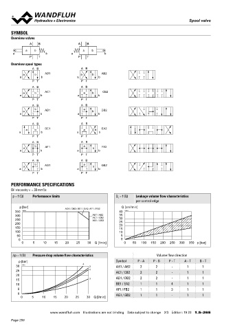
Overview valves
A B A B 2 28
45° 14
a b a b
a b a b 9.5
P T P T 5.2 P
10 30 MD= 2.6Nm MD= 5.2Nm
Overview spool types A B 14 27
A B A B 8 T T0
AB1
a
b
a a b b AB2 16 38
b
a
30
P T P T
A B A B 20
AC1
b
a
a a b b CB2 40.4 12 50 57.2 8.1
b
a
P T P T 77
A B A B 113.7
b AD1 a DB2
a
a b b
b
a
P T P T 4.1
A B A B 16
BE1
a
b
a a b b EA2
b
a
P T P T
A B A B
b AF1 a FB2 PARTS LIST ACCESSORIES
a
a b b
a
b
P T P T Position Article Description Fixing screws Data sheet 1.0-60
A B A B 10 160.8252 O-ring ID 25,12 x 1,78 (FKM) Threaded subplates Data sheet 2.9-10
b AG1 a GB2 20 253.6002 Mechanical control head BTII NG4 Multi-station subplates Data sheet 2.9-50
a
a b b 30 246.2119 Socket head screw M5 x 18 DIN 912 Horizontal mounting blocks Data sheet 2.9-90
b
a
P T P T
50 160.2052 O-ring ID 5,28 x 1,78 (NBR) Technical explanations Data sheet 1.0-100
160.6052 O-ring ID 5,28 x 1,78 (FKM) Filtration Data sheet 1.0-50
PERFORMANCE SPECIFICATIONS
Oil viscosity u = 30 mm /s
2
p = f (Q) Performance limits Q = f (Q) Leakage volume flow characteristics
L
per control edge SEALING MATERIAL STANDARDS
NBR or FKM (Viton) as standard, choice in the type code
p [bar] AD1 / DB2; BE1 / EA2; AF1 / FB2 Q [cm /min] Mounting interface Wandfluh standard
3
350 K4214 40 K1031 Contamination ISO 4406
300 AB1 / AB2 35 efficiency
250 AC1 / CB2 30
AG1 / GB2
200 25
20
150 15
100 10
50 5 INSTALLATION NOTES SURFACE TREATMENT
0 0
0 5 10 15 20 25 30 Q [l/min] 0 50 100 150 200 250 300 350 p [bar] Mounting type Flange mounting ◆ The valve body is painted with a two component paint
3 fixing holes for ◆ The roller housing and the cover are zinc-nickel coated
socket head screws M5 x 40
Δp = f (Q) Pressure drop volume flow characteristics Volume flow direction
Mounting position Any, preferably horizontal
p [bar] Symbol P - A P - B P - T A - T B - T Tightening torque Fixing screws M = 5,2 Nm (screw
D
30 K1029 4 2 AB1 / AB2 2 2 - 1 1 quality 8.8, zinc coated)
25 1 AC1 / CB2 2 2 - 1 1
20 Note! The length of the fixing screw depends on the base
15 3 AD1 / DB2 2 2 - 1 1 material of the connection element.
10 BE1 / EA2 1 1 4 1 1
5 AF1 / FB2 1 1 3 1 1
0 AG1 / GB2 1 1 - 1 1
0 5 10 15 20 25 30 Q [l/min]
Wandfluh AG Postfach CH-3714 Frutigen
Tel. +41 33 672 72 72 Fax +41 33 672 72 12 sales@wandfluh.com
www.wandfluh.com Illustrations are not binding Data subject to change 2/3 Edition: 19 23 1.5-26 E www.wandfluh.com Illustrations are not binding Data subject to change 3/3 Edition: 19 23 1.5-26 E
Page 258