Page 1098 - Softbound_Edition_19_en
P. 1098

Proportional                                                                                                                 Proportional
                                                                                         pressure relief valves
                                                                             Proportional pressure relief valve                               10                           20                                        pressure relief valves
                                                                                                                                                                                                                      54
                                                                                                                                                                                                                      48
                                                                                                                                         20                                                                           20,8
                                                                                                                                                                    P                                                  P
                                                                                                                                                    ∗
       SCREW-IN CARTRIDGES INSTALLED                                                                                               Proportional pressure relief valve  B   G1/4"   NG10                 ∗           A    B       ∗
                                                                                                                                                                 A
       The following screw-in cartridges are used in either the flange body or the sandwich body:                                  Flange and sandwich construction     To      60  ISO 4401-05    ♦           46  T       To  26,5  60
                                                                                                                                                                                          ♦
                                                                                                                                              ♦
                                                                                                                                                     60
                                                                                                                                                               T
                                                                                                                                   •  p    =  400 bar  38                   30  38  41                                            30  38
       Type        Designation                        Data sheet no.   Q max *                                                        max
       BVPPM22     pilot operated                           2.3-529   60 l/min                                                        30  70  40  6,5  Ø      70  115  45                                           A= 110  B= 1  10
       BNIPM22     pilot operated, inverse                  2.3-533   60 l/min                                                                                                                                       AB= 132
       BVBPM22     pilot operated, explosion proof Ex d     2.3-536   60 l/min
       BVPPM22-../ME  pilot operated, with integrated electronics   2.3-537   60 l/min
       BDPPM22     direct operated                          2.3-539   25 l/min
       BDIPM22     direct operated, inverse                 2.3-548   20 l/min
       BDBPM22     direct operated, explosion proof Ex d    2.3-547   25 l/min                                                                        ∗          ∗  P
       BDPPM22-../ME  direct operated, with integrated electronics   2.3-561   25 l/min                                               ♦       ♦                  A    B
       BDIPM22-../ME  direct operated, inverse, with integrated electronics   2.3-562   20 l/min                                                               T        To
       *   Can deviate from the values on the data sheets of the screw-in cartridges.
                                                                                                                                   DESCRIPTION                        FUNCTION                           APPLICATION
                                                                                                                                   Pilot operated proportional pressure relief   By adjusting the electric current to the pro-  The valves have their applications in hydraulic
       GENERAL SPECIFICATIONS                                         REMARK!                                                      valves  NG10. Flange and sandwich  con-  portional solenoid the operating pressure in   systems in which the pressure frequently has to
       Description       Pilot and direct operated proportional       Detailed  performance  data  and  additional  hydraulic      struction  according  to  ISO  4401-05  with  4   hydraulic systems is limited by reliefing the   be changed. The facility for remote control and
                         pressure relief valve                        and electric specifications may by drawn from the data       ports. Incorporated are proportional pressure   fluid from the protected lines P, A, B or A and   signal processing from process control systems
       Nominal size      NG6 according to ISO 4401-03                 sheets of the corresponding installed screw-in cartridge.    relief cartridges size M22x1,5 according to ISO   B to the return / tank line T. Back pressure in T   enable economical solutions to problems with
       Constructions     Flange or sandwich                                                                                        7789. The flange and sandwich bodies made   influences the pressure in the reliefed pressure   repeatable sequences.
       Operations        Proportional solenoid                                                                                     of steel are phosphatized.         lines. This proportional pressure relief valves
       Mounting          4 fixing holes for socket head cap screws    CAUTION!                                                                                        are adjustable very sensitivly. To control the
                         M5 or studs M5                               The performace data especially the „pressure-flow-                                              valve proportional amplifiers are available from
       Connections       Threaded connection plates                   characteristic„ on the data sheets of the screw-in                                              Wandfluh (see register 1.13).
                         Multi-flange subplates                       catridges refere to the screw-in cartridges only. The
                         Longitudinal stacking system                 additional press-ure drop of the flange body respectivly     TYPE CODE
       Weight:           • Flange type        m = 1,43 kg             sandwich body must be taken into consideration.                                                                    B           A10  -     -                    #
       (without screw-in cartridge)  • Sandwich type P, A, B   m = 1,18 kg
                         • Sandwich type AB   m = 1,58 kg                                                                          Pressure relief valve
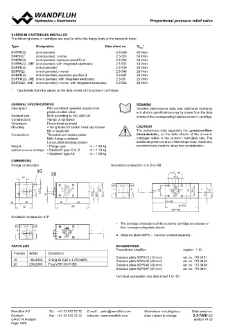
       DIMENSIONS                                                                                                                  2nd and 3rd digit position of the designation od the built-in cartridge
       Flange construction                               Sandwich construction in A, B or AB                                       Flange construction                  F
                    10                                                                                                             Sandwich construction                S
                           20                                                          21,5  19
            22                                                                           17,8                                      International standard interface ISO, NG10
                                                                                                                                   Type list / Function   flange construction    sandwich construction
                                 T                                                       T                                                                in P          P        in P          P
                                A     B        ∗
                  ♦  5,5                            45    ♦        ♦     ∗        31   A     B   21  32,5  ∗  45                                                                 in A          A
                     Ø    G1/4"                                                                                                                                                  in B          B
                         18      P              17,5  22,5                               P               22,5                                                                    in A and B    AB
      12      40               36       68                                           A= 102                                        Nominal pressure range, nominal voltage, etc., of the built-in cartridge
             52                      104                                                    B= 102                                 Design-Index (Subject to change)
                                                                                        AB= 140
       Sandwich construction in P
                                                            ∗  The envelop dimensions of the screw-in cartridge are shown on       Examples:  B V P F A10 – P –  20 – G24 / WD – HB4,5
                                  T                            their corresponding data sheets.                                             B D B S A10 – A – 100 - G12 / L15
         ♦        ♦             A     B        ∗                                                                                            B N I  S A10 – B –  200 – G24 / KD – D1
                                                            ♦  Distance plate ADP6/... must be ordered separatly.                           B V P S A10 – AB – 350 – G12 / ME A1 R1
                                 P
       PARTS LIST                                           ACCESSORIES
                                                            Proportional amplifier            register  1.13                       TYPE LIST / FUNCTION
        Position   Article   Description
                                                            Distance plate ADP6/12 (12 mm)    art. no. 173.3451                    Flange construction:   Sandwich construction:
        10      160.2093   O-ring ID 9,25 x 1,78 (NBR)      Distance plate ADP6/30 (30 mm)    art. no. 173.3453
        20      238.2406   Plug VSTI G1/4"-ED               Distance plate ADP6/46 (46 mm)    art. no. 173.3454
                                                            Distance plate ADP6/87 (87 mm)    art. no. 173.3461

                                                            Technical explanation see data sheet 1.0-100

                                                                                                                                   BV.FA10-P              BV.SA10 - P          BV.SA10 - A         BV.SA10 - B         BV.SA10 - AB


       Wandfluh AG        Tel.  +41 33 672 72 72   E-mail:  sales@wandfluh.com   Illustrations not obligatory   Data sheet no.     Wandfluh AG         Tel.  +41 33 672 72 72   E-mail:  sales@wandfluh.com   Illustrations not obligatory   Data sheet no.
       Postfach           Fax  +41 33 672 72 12   Internet:  www.wandfluh.com   Data subject to change   2.3-740E 2/2              Postfach            Fax  +41 33 672 72 12   Internet:  www.wandfluh.com   Data subject to change   2.3-760E 1/2
       CH-3714 Frutigen                                                                            Edition 14 02                   CH-3714 Frutigen                                                                             Edition 17 01
       Page 1098
   1093   1094   1095   1096   1097   1098   1099   1100   1101   1102   1103