
Page 1053 - Softbound_Edition_19_en
P. 1053
Proportional pressure reducing valve
Proportional pressure reducing valve
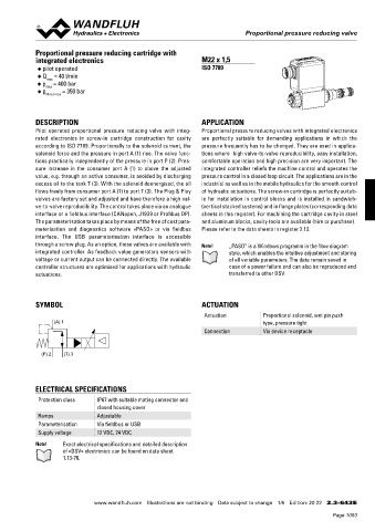
Proportional pressure reducing cartridge with
integrated electronics M22 x 1,5
◆ pilot operated ISO 7789
◆ Q = 40 l/min
max
◆ p = 400 bar
max
◆ p = 350 bar
N red max
DESCRIPTION APPLICATION
Pilot operated proportional pressure reducing valve with integ Proportional pressure reducing valves with integrated electronics
rated electronics in screwin cartridge construction for cavity are perfectly suitable for demanding applications in which the
according to ISO 7789. Proportionally to the solenoid current, the pressure frequently has to be changed. They are used in applica
solenoid force and the pressure in port A (1) rise. The valve func tions where high valvetovalve reproducibility, easy installation,
tions practically independently of the pressure in port P (2). Pres comfortable operation and high precision are very important. The
sure increase in the consumer port A (1) to above the adjusted integrated controller reliefs the machine control and operates the
value, e.g. through an active consumer, is avoided by discharging pressure control in a closed loop circuit. The applications are in the
excess oil to the tank T (3). With the solenoid deenergised, the oil industrial as well as in the mobile hydraulics for the smooth control
flows freely from consumer port A (1) to port T (3). The Plug & Play of hydraulic actuations. The screwin cartridge is perfectly suitab
valves are factory set and adjusted and have therefore a high val le for installation in control blocks and is installed in sandwich
vetovalve reproducibility. The control takes place via an analogue (vertical stacked systems) and in flange plates (corresponding data
interface or a fieldbus interface (CANopen, J1939 or Profibus DP). sheets in this register). For machining the cartridge cavity in steel
The parameterisation takes place by means of the free of cost para and aluminum blocks, cavity tools are available (hire or purchase).
meterisation and diagnostics software «PASO» or via fieldbus Please refer to the data sheets in register 2.13.
interface. The USB parameterisation interface is accessible
through a screw plug. As an option, these valves are available with Note! „PASO” is a Windows programm in the flow diagram
integrated controller. As feedback value generators sensors with style, which enables the intuitive adjustment and storing
voltage or current output can be connected directly. The available of all variable parameters. The data remain saved in
controller structures are optimised for applications with hydraulic case of a power failure and can also be reproduced and
actuations. transferred to other DSV.
SYMBOL ACTUATION
Actuation Proportional solenoid, wet pin push
(A) 1 type, pressure tight
Connection Via device receptacle
(P) 2 (T) 3
ELECTRICAL SPECIFICATIONS
Protection class IP67 with suitable mating connector and
closed housing cover
Ramps Adjustable
Parameterisation Via fieldbus or USB
Supply voltage 12 VDC, 24 VDC
Note! Exact electrical specifications and detailed description
of «DSV» electronics can be found on data sheet
1.1376.
www.wandfluh.com Illustrations are not binding Data subject to change 1/6 Edition: 20 22 2.3-643 E
Page 1053