Page 970 - Softbound_Edition_19_en
P. 970

Proportional pressure relief valve
                                                                             Proportional pressure relief valve                                                                                           Proportional pressure relief valve


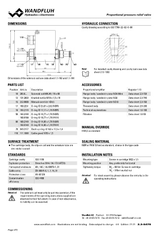
       DIMENSIONS                                          HYDRAULIC CONNECTION                                                    Proportional pressure relief cartridge inverse
                                                           Cavity drawing according to ISO 7789–22–02–0–98                          ◆  direct operated                                  M22 x 1,5
                                                                                                                                    ◆  Q  = 25 l/min                                    ISO 7789
                                                                                                                                       max
                                                                                 M22x1.5                                            ◆  p  = 400 bar
                                                                                                                                       max
               110                            s30                                                                                   ◆  p N max  = 350 bar
            70.8
         93.3                                M22x1.5                                      (2)
                15                                                                                                                 DESCRIPTION                                          APPLICATION
             MD=5.5Nm                          (2)
                                                    (1)                                                                            Direct  operated  proportional  pressure  relief  valve  with  inverse     The electrical remote control in conjunction with process controls
                                                                                          (1)                                      function in screw-in cartridge construction for cavity according to   allows economical solutions with repeatable processes. By means
            22.5                                                                                                                   ISO 7789. Good flow capacity due to the differencial area principle,   of  the  inverse  function,  the  maximum  system  pressure  is  main-
                                                                                  (1)                                              very sensitively adjustable. When the operating pressure adjusted   tained if the electrical valve control falls out (safety function).  The
                12     17   18    10  18    50  70    60
             MD=9Nm                                                                                                                by means of the proportional solenoid is reached, the valve opens   screw-in cartridge is perfectly suitable for installation in control
                                 60                        Note!    For detailed cavity drawing and cavity tools see data          and connects the protected line with the drain to the tank. With the   blocks and is installed in sandwich-  (vertical stacked systems) and
                                88.7           37                   sheet 2.13-1003                                                solenoid deenergised, maximum working pressure is present. If the   in  flange  plates  (corresponding  data  sheets  in  this  register).  For
                                   132.6                                                                                           solenoid current increases, the pressure in port P (1) drops. The   machining the cartridge cavity in steel and aluminum blocks, cavity
       Dimensions of the solenoid coil see data sheet 1.1-183 and 1.1-184
                                                                                                                                   back pressure in T (2) affects the pressure in P (1).  For the control,   tools  are  available  (hire  or  purchase).  Please  refer  to  the  data
                                                                                                                                   Wandfluh proportional amplifiers are available (see register 1.13).      sheets in register 2.13.
       PARTS LIST                                          ACCESSORIES
        Position Article  Description                       Proportional amplifier           Register 1.13
            10 263.6...  Solenoid coil MK.45 / 18 x 60      Flange body / sandwich plate NG4-Mini  Data sheet 2.3-720
            12 154.2603  Knurled nut Ex M18 x 1,5 x 18      Flange body / sandwich plate NG6  Data sheet 2.3-740                   SYMBOL                                               ACTUATION
            15 253.8000  Manual override HB4,5              Flange body / sandwich plate NG10  Data sheet 2.3-760                                                                        Actuation          Proportional solenoid, wet pin push
            17 160.2251  O-ring ID 25,07 x 2,62 (NBR)       Threaded body                    Data sheet 2.9-200                        (T) 2                                                                type, pressure tight
            18 160.2170  O-ring ID 17,17 x 1,78 (NBR)       Technical explanations           Data sheet 1.0-100                                                                          Execution          W.S37 / 19 x 50 (Data sheet 1.1-173)
            50 160.2188  O-ring ID 18,77 x 1,78 (NBR)       Filtration                       Data sheet 1.0-50                                                                                              M.S35 / 19 x 50 (Data sheet 1.1-174)
               160.8188  O-ring ID 18,77 x 1,78 (FKM)                                                                                                                                    Connection         Connector socket EN 175301 – 803
            60 160.2140  O-ring ID 14,00 x 1,78 (NBR)                                                                                       (P) 1                                                           Connector socket AMP Junior-Timer
               160.8140  O-ring ID 14,00 x 1,78 (FKM)                                                                                                                                                       Connector Deutsch DT04 – 2P
            70 049.3177  Back-up ring rd 14,6 x 17,5 x 1,4  MANUAL OVERRIDE                                                        TYPE CODE
                                                           HB4,5 as standard
           110 111.1080  Cable gland M20 x 1,5
                                                                                                                                                                                                  B  D  I  PM22  -     -     /        -     #
                                                                                                                                    Pressure relief valve
       SURFACE TREATMENT                                   SEALING MATERIAL                                                         Direct operated
       ◆  The cartridge body, the slip-on coil and the armature tube are   NBR or FKM (Viton) as standard, choice in the type code
         zinc-nickel coated                                                                                                         Proportional, inverse

       STANDARDS                                           INSTALLATION NOTES                                                       Screw-in cartridge M22 x 1,5
       Cartridge cavity   ISO 7789                          Mounting type      Screw-in cartridge M22 x 1,5                         Nominal pressure range p    20 bar   20     200 bar     200
       Explosion protection  Directive 2014 / 34 / EU (ATEX)  Mounting position  Any, preferably horizontal                                          N     100 bar      100     315 bar     315
       Flameproof enclosure  EN / IEC / UL 60079-1, 31      Tightening torque  M  = 60 Nm Screw-in cartridge                                               160 bar      160     350 bar     350
                                                                                D
       Cable entry        EN 60079-0, 1, 7, 15, 31                             M  = 9 Nm knurled nut                                Nominal voltage U      12 VDC       G12
                                                                                D
       Protection class   EN 60 529                        Attention!  For stack assembly please observe the remarks in the                     N          24 VDC       G24
       Contamination      ISO 4406                                  operating instructions                                                                 without coil   X5
       efficiency                                                                                                                   Slip-on coil           Metal housing round              W
                                                                                                                                                           Metal housing square             M
       COMMISSIONING
       Attention!  The solenoid coil must only be put into operation, if the                                                        Connection execution   Connector socket EN 175301-803 / ISO 4400   D
                 requirements of the operating instructions supplied are                                                                                   Connector socket AMP Junior - Timer   J
               observed to their full extent. In case of non-observance,                                                                                   Connector Deutsch DT04 - 2P      G
               no liability can be assumed.                                                                                         Sealing material       NBR
                                                                                                                                                           FKM (Viton)   D1

                                                                                                                                    Design index (subject to change)
                                                           Wandfluh AG  Postfach  CH-3714 Frutigen                                  2.3-548
                                                           Tel. +41 33 672 72 72  Fax +41 33 672 72 12  sales@wandfluh.com

                         www.wandfluh.com  Illustrations are not binding  Data subject to change  4/4  Edition: 21 21  2.3-547 E                      www.wandfluh.com  Illustrations are not binding  Data subject to change  1/4  Edition: 19 29  2.3-548 E
       Page 970
   965   966   967   968   969   970   971   972   973   974   975