Page 947 - Softbound_Edition_19_en
P. 947

Proportional pressure relief valve
                                                                                   Proportional pressure relief valve


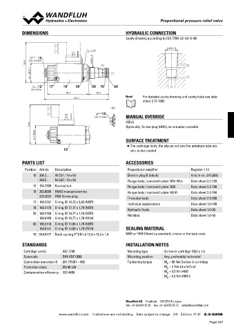
            DIMENSIONS                                           HYDRAULIC CONNECTION
                                                                 Cavity drawing according to ISO 7789–22–02–0–98

                                                                                       M22x1.5
                                                s30
                    15                          M22x1.5
               76.8   MD=5.5Nm                      (2)                                         (2)
                 37.1
                                                          (1)
                  W =                                                                           (1)
                    12    17     10    18       50  70     60                          (1)
                 MD=5Nm
                                   78.4            38.5
                                       123.1                     Note!    For detailed cavity drawing and cavity tools see data
                                                                          sheet 2.13-1003

                                                         HB0
                                                     15
                                                 MD= 9.5Nm       MANUAL OVERRIDE
                 74.8                                            HB4,5
                                                                 Optionally: Screw plug (HB0), no actuation possible
                   35
                    M =                                          SURFACE TREATMENT

                                                                  ◆  The cartridge body, the slip-on coil and the armature tube are
                                 10                                zinc-nickel coated


            PARTS LIST                                           ACCESSORIES
              Position Article  Description                       Proportional amplifier          Register 1.13
                  10 206.2…  W.S37 / 19 x 50                      Electric plug B (black)         Article no. 219.2002
                     260.5…  M.S35 / 19 x 50                      Flange body / sandwich plate NG4-Mini  Data sheet 2.3-720
                  12 154.2700  Knurled nut                        Flange body / sandwich plate NG6  Data sheet 2.3-740
                  15 253.8000  HB4,5 manual override              Flange body / sandwich plate NG10  Data sheet 2.3-760
                     239.2033  HB0 Screw plug                     Threaded body                   Data sheet 2.9-200
                  17 160.2187  O-ring ID 18,72 x 2,62 (NBR)
                                                                  Technical explanations          Data sheet 1.0-100
                  18 160.2170  O-ring ID 17,17 x 1,78 (NBR)       Hydraulic fluids                Data sheet 1.0-50
                  50 160.2188  O-ring ID 18,77 x 1,78 (NBR)       Filtration                      Data sheet 1.0-50
                     160.6188  O-ring ID 18,77 x 1,78 (FKM)
                  60 160.2140  O-ring ID 14,00 x 1,78 (NBR)
                     160.6141  O-ring ID 14,00 x 1,78 (FKM)      SEALING MATERIAL
                  70 049.8177  Back-up ring PTSM rd 12,4 x 15,3 x 1,4  NBR or FKM (Viton) as standard, choice in the type code

            STANDARDS                                            INSTALLATION NOTES
             Cartridge cavity    ISO 7789                         Mounting type      Screw-in cartridge M22 x 1,5
             Solenoids           DIN VDE 0580                     Mounting position  Any, preferably horizontal
             Connection execution D  EN 175301 – 803              Tightening torque  M  = 60 Nm Screw-in cartridge
                                                                                      D
             Protection class    EN 60 529                                           M  = 5 Nm knurled nut
                                                                                      D
             Contamination efficiency  ISO 4406                                      M  = 9,5 Nm HB0
                                                                                      D
                                                                                     M  = 5,5 Nm HB4,5
                                                                                      D


                                                                 Wandfluh AG  Postfach  CH-3714 Frutigen
                                                                 Tel. +41 33 672 72 72  Fax +41 33 672 72 12  sales@wandfluh.com

                               www.wandfluh.com  Illustrations are not binding  Data subject to change  3/3  Edition: 17 41  2.3-529 E
                                                                                                            Page 947
   942   943   944   945   946   947   948   949   950   951   952