
Page 856 - Softbound_Edition_19_en
P. 856
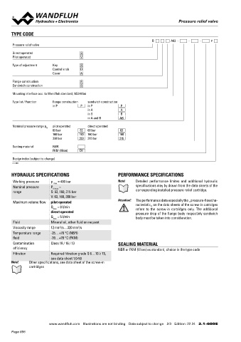
Pressure relief valve
Pressure relief valve Pressure relief valve
TYPE CODE VALVES INSTALLED
B A03 - - - # The following screw-in cartridges are used in either the flange body or the sandwich body.
Pressure relief valve
Article Description Data sheet no.
Direct operated S BV.PM18 Pressure relief cartridge pilot operated 2.1-510
Pilot operated V
BS.PM18 Pressure relief cartridge direct operated 2.1-520
Type of adjustment Key S
Control knob D DIMENSIONS
Cover A Flange execution Sandwich execution
B.DFA03-P B.DSA03-P
Flange construction F
Sandwich construction S MD= 2.6Nm 30 29.5
7.5 5 25 4.3 P
Mounting interface acc. to Wandfluh standard, NG3-Mini
A B 30
P 15 T To
Type list / Function flange construction sandwich construction A B 30
in P P in P P 17.5 15 T To 15 MD= 30Nm 10 20 MD=18Nm
in A A 15 10 48 80 5
in B B MD=30Nm 35 20 MD= 18Nm
in A and B AB 51.8 67 5
Nominal pressure range p N pilot operated direct operated
63 bar 63 63 bar 63 Sandwich execution Type of adjustment Type of adjustment
160 bar 160 160 bar 160
B.DSA03-A / B / AB B.S.A03 B.A.A03
350 bar 350 315 bar 315
P
Sealing material NBR A B 30
FKM (Viton) D1 T To s4
10 MD= 30Nm MD=30Nm
Design index (subject to change) MD=30Nm 48 30 MD=18Nm 44 50
2.1-600 96 11.7
B.DSA03-A: Cartridge on A side
B.DSA03-B: Cartridge on B side
HYDRAULIC SPECIFICATIONS PERFORMANCE SPECIFICATIONS
B.DSA03-AB: Cartridge on A and B side
Working pressure p = 400 bar Note! Detailed performance limites and additional hydraulic
max
Nominal pressure P N max = specifications may by drawn from the data sheets of the HYDRAULIC CONNECTION PARTS LIST
range S: 63, 160, 315 bar corresponding installed pressure relief cartridge.
V: 63, 160, 350 bar Position Article Description
Attention! The performance data especially the „pressure-flowcha-
Maximum volume flow pilot operated racteristic„ on the data sheets of the screw-in catridges P 10 160.2045 O-ring ID 4,50 x 1,50 (NBR)
Q = 8 l/min A B 160.6045 O-ring ID 4,50 x 1,50 (FKM)
max refere to the screw-in cartridges only. The additional 11 21
direct operated pressure drop of the flange body respectivly sandwich T T 0 20 238.2406 Screw plug VSTI G1/4"-ED
Q = 5 l/min body must be taken into consideration.
max 30 239.3011 Screw plug M18 x 1,5
Fluid Mineral oil, other fluid on request 10
Viscosity range 12 mm /s…320 mm /s 20
2
2
Temperature range -25…+70 °C (NBR)
fluid -20…+70 °C (FKM)
Contamination Class 18 / 16 / 13 SEALING MATERIAL
efficiency NBR or FKM (Viton) as standard, choice in the type code INSTALLATION NOTES ACCESSORIES
Filtration Required filtration grade ß 6…10 ≥ 75,
see data sheet 1.0-50 Mounting type Flange or sandwich mounting Verstellarten für Schraubpatronen Data sheet 2.0-50
Note! Other specifications, see data sheet of the screw-in 3 fixing holes for Threaded subplates Data sheet 2.9-05
cartridges socket head screws or stud M4 Multi-station subplates Data sheet 2.9-45
Mounting position Any, preferably horizontal Horizontal mounting blocks Data sheet 2.9-85
Tightening torque Fixing screws M = 2,6 Nm (quality 8.8,
D
zinc coated) Technical explanations Data sheet 1.0-100
Screw-in cartridge M = 30 Nm Filtration Data sheet 1.0-50
D
Wandfluh AG Postfach CH-3714 Frutigen
Tel. +41 33 672 72 72 Fax +41 33 672 72 12 sales@wandfluh.com
www.wandfluh.com Illustrations are not binding Data subject to change 2/3 Edition: 22 24 2.1-600 E www.wandfluh.com Illustrations are not binding Data subject to change 3/3 Edition: 22 24 2.1-600 E
Page 856