
Page 759 - Softbound_Edition_19_en
P. 759
Mobile electronics
Mobile electronics MD2
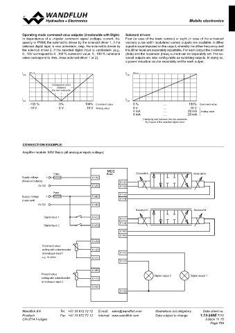
Operating mode command value unipolar (2-solenoids with DigIn) Solenoid drivers
In dependence of a unipolar command signal (voltage, current, fre- Four (in case of the basic version) or eight (in case of the enhanced
quency or PWM) the solenoid is driven by the solenoid driver 1, if the version) pulse width modulated current outputs are available. A dither
selected digital input is «not activated», resp. the solenoid is driven by signal is superimposed on the output, whereby the dither frequency and
the solenoid driver 2, if the selected digital input is «activated» (e.g., the dither level are separately adjustable. For each output the minimum
0...10V correspond to 0...100 % command value, 0...100 % command (Imin) and the maximum (Imax) current can be separately set. The so-
value correspond to Imin...Imax solenoid driver 1 or 2). lenoid outputs are also configurable as switching outputs. In doing so,
a power reduction can be separately set for each output.
I K0931_e.ai I K0933_e.ai
max max
Changeover point
between
the two solenoids
↓
I I
min min
-100 % 0% 100% Command value 0 % ... 100% Command value
-10 V 0 V 10 V Analog value 0 V ... 10 V
4 mA ... 20 mA Analog value
0 mA ... 20 mA
Changing over between the two solenoids
by means of the selected digital input
CONNECTION EXAMPLE:
Amplifier module: MD2 Basic (all analogue inputs voltage):
MD2
Fuse Basic Solenoid A Solenoid B MD2
Supply voltage + X1-A2 Fuse Enhanced Solenoid A Solenoid B
(Solenoid outputs) X1-G1 Supply voltage + X1-A2
0V DC X1-A3 X1-G2 (Solenoid outputs) X1-G1
0V DC X1-A3 X1-G2
Fuse
Supply voltage + X1-B2 X1-H1 Fuse X1-H1
X1-H2
(Logic part) Supply voltage + X1-B2 X1-H2
0V DC X1-B3 (Logic part)
0V DC X1-B3
Solenoid C Solenoid D
Solenoid C Solenoid D
Digital input 1 X1-C2
X1-J1 Digital input 1 X1-C2
X1-J2 X1-J1
Digital input 2 X1-C3 X1-J2
Digital input 2 X1-C3
X1-K1
X1-K2 X1-K1
Digital input 3 X2-E1
X1-K2
X1-A1
Command value Digital input 4 X2-E2
setting with potentiometer X1-E1 Solenoid E Solenoid F
at analogue input 1 X1-F2
e.g. 10 kOhm X1-C1 X2-A1
X1-F3 X1-A1 X2-A2
Command value
X1-B1 setting with potentiometer X2-B1
Present value Digital output 2 Digital output 1 at analogue input 1 X1-E1 X2-B2
setting with potentiometer X1-F1
at analogue input 2
X1-D1 at analogue input 2
X1-G3 X1-F1 Solenoid G
X2-C1
X1-C1 X2-C2
Wandfluh AG Tel. +41 33 672 72 72 E-mail: sales@wandfluh.com Illustrations not obligatory Data sheet no.
Postfach Fax +41 33 672 72 12 Internet: www.wandfluh.com Data subject to change 1.13-240E 7/10
CH-3714 Frutigen Edition 11 15
Page 759 Solenoid H
X2(only for Enhanced Version) X1
X1-B1 X2-D1
A B C D E F A B C D E F G H J K X2-D2
1 1 1 1
2 2 2 2 at analogue input 3
3 3 3 3 X2-F1
X1-F2
at analogue input 4
X2-F2 X1-F3
Digital output 2 Digital output 1
X1-D1
2 1
X1-G3
3 4