
Page 649 - Softbound_Edition_19_en
P. 649
Poppet valve
Poppet valve
VALVES INSTALLED
The central functioning element is the poppet valve cartridge NG10, data sheet 1.11-2040.
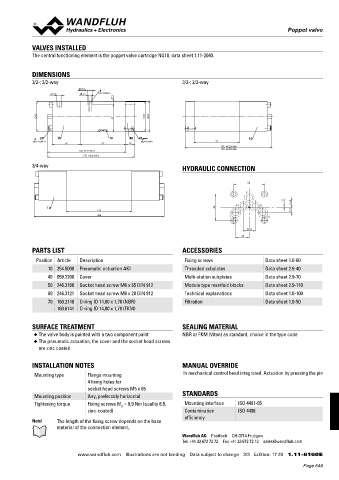
DIMENSIONS
3/2-; 2/2-way 3/2-; 2/2-way
10.5
G1/8" 6.5 MD= 8.9Nm
7
60 60 62
55
50 10 70 40 60 10
MD= 8.9Nm MD= 8.9Nm 93
57 93 18
178 AK22100b
178 AK32100b
160 AK22101a
178 AK32101a
3/4-way HYDRAULIC CONNECTION
54
P
1.5
A B 16.8
10 46
133 9.7
266 T To
20.8
24
PARTS LIST ACCESSORIES
Position Article Description Fixing screws Data sheet 1.0-60
10 254.5000 Pneumatic actuation AKI Threaded subplates Data sheet 2.9-40
40 059.2200 Cover Multi-station subplates Data sheet 2.9-70
50 246.3166 Socket head screw M6 x 65 DIN 912 Module type manifold blocks Data sheet 2.9-110
60 246.3121 Socket head screw M6 x 20 DIN 912 Technical explanations Data sheet 1.0-100
70 160.2140 O-ring ID 14,00 x 1,78 (NBR) Filtration Data sheet 1.0-50
160.6141 O-ring ID 14,00 x 1,78 (FKM)
SURFACE TREATMENT SEALING MATERIAL
◆ The valve body is painted with a two component paint NBR or FKM (Viton) as standard, choice in the type code
◆ The pneumatic actuation, the cover and the socket head screws
are zinc coated
INSTALLATION NOTES MANUAL OVERRIDE
Mounting type Flange mounting In mechanical control head integrated. Actuation by pressing the pin
4 fixing holes for
socket head screws M5 x 65
Mounting position Any, preferably horizontal STANDARDS
Tightening torque Fixing screws M = 8,9 Nm (quality 8.8, Mounting interface ISO 4401-05
D
zinc-coated) Contamination ISO 4406
efficiency
Note! The length of the fixing screw depends on the base
material of the connection element.
Wandfluh AG Postfach CH-3714 Frutigen
Tel. +41 33 672 72 72 Fax +41 33 672 72 12 sales@wandfluh.com
www.wandfluh.com Illustrations are not binding Data subject to change 3/3 Edition: 17 20 1.11-6160 E
Page 649