
Page 267 - Softbound_Edition_19_en
P. 267
Spool valve
Spool valve
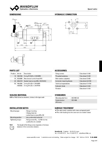
DIMENSIONS HYDRAULIC CONNECTION
2.6 17.8
T
9.5
45°
10 30 MD= 5.2Nm 5.2 MD= 5.2Nm 8 31 A B 21 32.5
P
21.5
40.5
16 49
41
20 11 50
39.8 68 12.6
81.8
128.4
4.1
16
PARTS LIST ACCESSORIES
Position Article Description Fixing screws Data sheet 1.0-60
10 160.2236 O-ring ID 23,52 x 1,78 (NBR) Threaded subplates Data sheet 2.9-30
20 253.6000 Mechanical control head ATII Multi-station subplates Data sheet 2.9-60
30 246.2119 Socket head screw M5 x 18 DIN 912 Horizontal mounting blocks Data sheet 2.9-100
50 160.2093 O-ring ID 9,25 x 1,78 (NBR) Technical explanations Data sheet 1.0-100
160.6092 O-ring ID 9,25 x 1,78 (FKM) Hydraulic fluids Data sheet 1.0-50
Filtration Data sheet 1.0-50
SEALING MATERIAL STANDARDS
NBR or FKM (Viton) as standard, choice in the type code Mounting interface ISO 4401-03
Contamination ISO 4406
efficiency
INSTALLATION NOTES SURFACE TREATMENT
Mounting type Flange mounting ◆ The valve body is painted with a two component paint
4 fixing holes for ◆ The roller housing and the cover are zinc-nickel coated
socket head screws M5 x 50
Mounting position Any, preferably horizontal
Tightening torque Fixing screws M = 5,2 Nm (screw
D
quality 8.8, zinc coated)
Note! The length of the fixing screw depends on the base
material of the connection element.
Wandfluh AG Postfach CH-3714 Frutigen
Tel. +41 33 672 72 72 Fax +41 33 672 72 12 sales@wandfluh.com
www.wandfluh.com Illustrations are not binding Data subject to change 3/3 Edition: 18 18 1.5-46 E
Page 267