Page 1175 - Softbound_Edition_19_en
P. 1175
Flow control valves
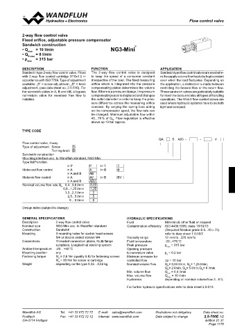
                                                                                                 Flow control valve

            2-way flow control valve
            Fixed orifice, adjustable pressure compensator
            Sandwich construction                                    ®
            • Q max   = 10 l/min                         NG3-Mini
            • Q N max  = 8 l/min
            • p    = 315 bar
               max
            DESCRIPTION                        FUNCTION                           APPLICATION
            Sandwich type 2-way flow control valve. Fitted   The  2-way  flow  control  valve  is  designed   Sandwich type flow control valves are used whe-
            with 2-way flow control cartridge M18x1,5 in   to  keep  the  speed  of  a  consumer  constant   re the supply volume flow has to be kept constant
            accordance with ISO 7789. Type of adjustment   irrespective of the load. The fixed measuring   even when the load fluctuates. Depending on
            available: „S“ = screw adjustment, „D“ = knob   orifice which is integrated into the pressure   the application, a distinction is made between
            adjustment, (see data sheet no. 2.5-510). For   compensating piston determines the volume   restricting the forward flow or the return flow.
            the sandwich plates in A, B and AB, a bypass   flow. If there is a pressure change, the pressure   These sandwich valves are particularly suitable
            non-return  valve  for  reversed  free  flow  is   compensating spool is displaced and changes   for machine tools and also all types of handling
            installed.                         the outlet diameter in order to keep the pres-  operations. The Mini-3 flow control valves are
                                               sure difference across the measuring orifice   used where hydraulic systems have to be both
                                               constant.  By  varying  the  spring  bias  acting   light and compact.
                                               on the compensator spool, the flow rate can
                                               be changed. Minimum adjustable flow within
                                               40…70 % of Q . Flow regulation is effective
                                                          N
                                               above ∆p 10 bar approx.
            TYPE CODE

                                                                                 QA      S  A03  -    -       #
            Flow control valve, 2-way
            Type of adjustment  Screw   S
                           Turning knob  D
            Sandwich construction
            Mounting interface acc. to Wandfluh standard, NG3-Mini
            Type list/Function
                                   in P       P     in T     T
            Meter-out flow control   in A     A     in B     B
                                   in A and B    AB
            Meter-in flow control   in A      AV    in B     BV
                                   in A and B   ABV
            Nominal volume flow rate Q   0,4...0,6 l/min   0,63
                                N
                                 0,8...1,25 l/min   1,25
                                  1,3...2,1 l/min   2
                                   2,5...5 l/min   5
                                    5 ...8 l/min   8
            Design index (subject to change)

            GENERAL SPECIFICATIONS                               HYDRAULIC SPECIFICATIONS
            Description      2-way flow control valve            Fluid               Mineral oil, other fluid on request
            Nominal size      NG3-Mini acc. to Wandfluh standard  Contamination efficiency  ISO 4406:1999, class 18/16/13
            Construction      Sandwich                                               (Required filtration grade ß 6...10 ≥ 75)
            Mounting         3 mounting holes for socket head screws                 refer to data sheet 1.0-50/2
                             M  4   or double ended screws M4    Viscosity range     12 mm /s...320 mm /s
                                                                                          2
                                                                                                  2
            Connections      Threaded connection plates, Multi-flange   Fluid temperature   -20...+70 °C
                             subplates, Longitudinal stacking system  Peak pressure       p  max  = 315 bar
            Ambient temperature   -20…+50 °C                     Opening pressure
            Mounting position   any                              to non-return valve   p  = 0,2 bar
                                                                                      ö
            Fastening torque   M = 2,8 Nm (quality 8.8) for fastening screws  Minimum pressure for
                               D
                             M  D  = 30 Nm for screw-in cartridge   controlled flow     ∆p = 10 bar
            Weight           depending on the type 0,32…0,42 kg  Nominal volume flow   Q = 0,63 l/min, Q = 1,25 l/min,
                                                                                                 N
                                                                                      N
                                                                                     Q  N = 2 l/min, Q = 5 l/min,Q = 8 l/min
                                                                                               N
                                                                                                       N
                                                                 Min. volume flow    Q  = 0,4 l/min
                                                                                      min
                                                                 Max. volume flow    Q max  = 10 l/min
                                                                 Hysteresis          depending on nominal volumeflow 3...8 %
                                                                 For further hydraulic specifications refer to data sheet 2.5-510.

            Wandfluh AG         Tel.  +41 33 672 72 72   E-mail:  sales@wandfluh.com   Illustrations not obligatory   Data sheet no.
            Postfach            Fax  +41 33 672 72 12   Internet:  www.wandfluh.com   Data subject to change   2.5-700E 1/2
            CH-3714 Frutigen                                                                             Edition 21 31
                                                                                                           Page 1175

