Page 1062 - Softbound_Edition_19_en
P. 1062

Proportional pressure reducing valve
                                                                         Proportional pressure reducing valve                                                                                          Proportional pressure reducing valve


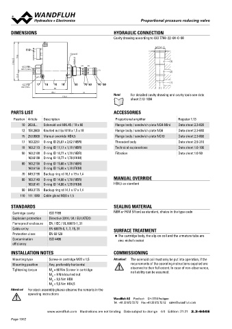
       DIMENSIONS                                          HYDRAULIC CONNECTION                                                    Proportional pressure reducing cartridge
                                                           Cavity drawing according to ISO 7789–22–04–0–98                          ◆  pilot operated                                   M33 x 2
                                                                                                                                    ◆  Q  = 160 l/min                                   ISO 7789
                                                                                                                                       max
                                                                                 M22x1.5                                            ◆  p  = 400 bar
              110                                                                                                                      max
                                                                                                                                    ◆  p    = 350 bar
                                       s30                                                                                             N red max
           70.8
         93.3                          M22x1.5                                          (3)
               15                          (3)  (2)
            MD=5.5Nm                               (1)
                                                                                        (2)
           22.5                                                                                                                    DESCRIPTION                                          APPLICATION
                                                                                        (1)
               12   17  18   10  18    50   70  60  90  80                                                                         Pilot  operated  proportional  pressure  reducing  valve  in  screw-in   The electrical remote control in conjunction with process controls
            MD=9Nm
                             60                                                   (1)                                              cartridge construction for cavity according to ISO 7789. Proportio-  allows  economical  solutions  with  repeatable  processes.  The
                            88.7            61                                                                                     nally to the solenoid current, the solenoid force and the pressure in   screw-in cartridge is perfectly suitable for installation in control
                                                           Note!    For detailed cavity drawing and cavity tools see data
                                  156.6                                                                                            port A (1) rise. The valve functions practically independently of the   blocks. For machining the cartridge cavity in steel and aluminum
                                                                    sheet 2.13-1004                                                pressure in port P (2). Pressure increase in the consumer port A (1)   blocks, cavity tools are available (hire or purchase). Please refer to
                                                                                                                                   to above the adjusted value, e.g. through an active consumer, is   the data sheets in register 2.13.


       PARTS LIST                                          ACCESSORIES                                                             avoided by discharging excess oil to the tank T (3). With the sole-
                                                                                                                                   noid deenergised, the oil flows freely from port P (2) to consumer
        Position Article  Description                       Proportional amplifier           Register 1.13
                                                                                                                                   port  A  (1).  For  the  control,  Wandfluh  proportional  amplifiers  are
            10 263.6...  Solenoid coil MK.45 / 18 x 60      Flange body / sandwich plate NG4-Mini  Data sheet 2.3-820              available (see register 1.13).

            12 154.2603  Knurled nut Ex M18 x 1,5 x 18      Flange body / sandwich plate NG6  Data sheet 2.3-840
            15 253.8000  Manual override HB4,5              Flange body / sandwich plate NG10  Data sheet 2.3-860
            17 160.2251  O-ring ID 25,07 x 2,62 (NBR)       Threaded body                    Data sheet 2.9-210
            18 160.2170  O-ring ID 17,17 x 1,78 (NBR)       Technical explanations           Data sheet 1.0-100
            50 160.2188  O-ring ID 18,77 x 1,78 (NBR)       Filtration                       Data sheet 1.0-50                     SYMBOL                                               ACTUATION

               160.6188  O-ring ID 18,77 x 1,78 (FKM)                                                                                                                                    Actuation          Proportional solenoid, wet pin push
                                                                                                                                           (A) 1                                                            type, pressure tight
            60 160.2156  O-ring ID 15,60 x 1,78 (NBR)
               160.6156  O-ring ID 15,60 x 1,78 (FKM)                                                                                                                                    Execution          W.S37 / 19 x 50 (Data sheet 1.1-173)
            70 049.3196  Backup ring rd 16,1 x 19 x 1,4                                                                                                                                  Connection         M.S35 / 19 x 50 (Data sheet 1.1-174)
                                                                                                                                                                                                            Connector socket EN 175301 – 803
            80 160.2140  O-ring ID 14,00 x 1,78 (NBR)      MANUAL OVERRIDE                                                           (P) 2  (T) 3                                                           Connector socket AMP Junior-Timer
               160.6141  O-ring ID 14,00 x 1,78 (FKM)      HB4,5 as standard                                                                                                                                Connector Deutsch DT04 – 2P
            90 049.3176  Backup ring rd 14,1 x 17 x 1,4
           110 111.1080  Cable gland M20 x 1,5

       STANDARDS                                           SEALING MATERIAL
       Cartridge cavity   ISO 7789                         NBR or FKM (Viton) as standard, choice in the type code
       Explosion protection  Directive 2014 / 34 / EU (ATEX)                                                                       STANDARDS                                            INSTALLATION NOTES
       Flameproof enclosure  EN / IEC / UL 60079-1, 31                                                                              Cartridge cavity    ISO 7789                         Mounting type      Screw-in cartridge M33 x 2
       Cable entry        EN 60079-0, 1, 7, 15, 31         SURFACE TREATMENT                                                        Solenoids           DIN VDE 0580                     Mounting position  Any, preferably horizontal
       Protection class   EN 60 529                                                                                                 Connection execution D  EN 175301 – 803              Tightening torque  M  = 80 Nm Screw-in cartridge
                                                            ◆  The cartridge body, the slip-on coil and the armature tube are                                                                                D
       Contamination      ISO 4406                            zinc-nickel coated                                                    Protection class    EN 60 529                                           M  = 5 Nm knurled nut
                                                                                                                                                                                                             D
       efficiency                                                                                                                   Contamination efficiency ISO 4406
       INSTALLATION NOTES                                  COMMISSIONING
       Mounting type      Screw-in cartridge M22 x 1,5     Attention!    The solenoid coil must only be put into operation, if the
       Mounting position  Any, preferably horizontal                requirements of the operating instructions supplied are
       Tightening torque  M  = 60 Nm Screw-in cartridge             observed to their full extent. In case of non-observance,
                                                                    no liability can be assumed.
                            D
                          M  = 9 Nm knurled nut
                            D
                          M  = 9,5 Nm HB0
                            D
                          M  = 5,5 Nm HB4,5
                            D
       Attention!  For stack assembly please observe the remarks in the
               operating instructions
                                                           Wandfluh AG  Postfach  CH-3714 Frutigen
                                                           Tel. +41 33 672 72 72  Fax +41 33 672 72 12  sales@wandfluh.com
                         www.wandfluh.com  Illustrations are not binding  Data subject to change  4/4  Edition: 21 21  2.3-644 E                      www.wandfluh.com  Illustrations are not binding  Data subject to change  1/4  Edition: 17 48  2.3-649 E
       Page 1062
   1057   1058   1059   1060   1061   1062   1063   1064   1065   1066   1067